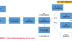
中小型網絡項目建設案例
VLAN及IP地址規劃

vlan1   無(vlan名稱)    192.168.0.0/24 (ip網段)  192.168.0.254(默認網關)  管理VLAN
vlan10   JWC              192.168.1.0/24             192.168.1.254
vlan20   XSSS             192.168.2.0/24             192.168.2.254
vlan30   CWC              192.168.3.0/24             192.168.3.254
vlan40   JGSS             192.168.4.0/24             192.168.4.254
vlan50   JZX              192.168.5.0/24             192.168.5.254
vlan60   GLX              192.168.6.0/24             192.168.6.254
vlan70   JSJX             192.168.7.0/24             192.168.7.254
vlan100  FWQQ             192.168.100.0/24           192.168.100.254           服務器群VLAN
一、接入層交換機配置
本次實驗中接入層只有2臺,本文只配置AWS1,像AWS2、AWS3、AWS4等就不寫成操作命令。
1.為訪問層交換機命名為ASW1
- Switch>enable
- Switch#config terminal
- Switch(config)#hostname ASW1
2.將交換機設置加密口令123
- ASW1(config)#enable secret 123
3.設置登錄交換機時的口令cisco
- ASW1(config)#line vty 0 15
- ASW1(config-line)#login
- ASW1(config-line)#password cisco
4.設置終端線超時時間
- ASW1(config-line)#line vty 0 15
- ASW1(config-line)#exec-timeout 5 30
- ASW1(config-line)#line con 0
- ASW1(config-line)#exec-timeout 5 30
5.設置禁用IP地址解析特性
- ASW1(config-line)#no ip domain-lookup
6.設置啟用消息同步特性
- ASW1(config)#line con 0
- ASW1(config-line)#logging synchronous
- ASW1(config-line)#exit
7.配置訪問層交換機ASW1的管理IP和默認網關
- ASW1(config)#interface vlan 1
- ASW1(config-if)#ip address 192.168.0.5 255.255.255.0
- ASW1(config-if)#no shutdown
- ASW1(config)#ip default-gateway 192.168.0.254
8.配置訪問層ASW1的VLAN及VTP
- ASW1(config)#vtp mode client
- ASW1(config)#interface range fastethernet0/1 - 24
- ASW1(config-if-range)#duplex full
- ASW1(config-if-range)#speed 100
9.配置訪問層交換機ASW1的訪問端口1-10
- ASW1(config-if-range)#interface range fastethernet0/1 - 10
- ASW1(config-if-range)#switchport mode access
- ASW1(config-if-range)#switchport access vlan 10
- ASW1(config-if-range)#exit
10.配置訪問層交換機ASW1的訪問端口11-20
- ASW1(config)#interface range fastethernet0/11 - 20
- ASW1(config-if-range)#switchport mode access
- ASW1(config-if-range)#switchport access vlan 20
- ASW1(config-if-range)#exit
11.設置快速端口
- ASW1(config)#interface range fastethernet0/1 - 20
- ASW1(config-if-range)#spanning-tree portfast
12.設置主干道端口
- ASW1(config-if-range)#interface range fastethernet 0/23 - 24
- ASW1(config-if-range)#switchport mode trunk
13.訪問層交換機ASW2為VLAN30和VLAN40的用戶提供接入服務。
分別通過F0/23、F0/24上連到分布層交換機DSW1、DSW2的端口F0/24#p#
二、配置分布層交換機DSW1的基本參數。(直接寫出命令,不再寫出說明)
1.DSW1的基本參數。(直接寫出命令,不再寫出說明)
- Switch>en
- Switch#config terminal
- Switch(config)#hostname DSW1
- DSW1(config)#enable secret 456
- DSW1(config)#line con
- DSW1(config)#line console 0
- DSW1(config-line)#logging synchronous
- DSW1(config-line)#exec-timeout 5 30
- DSW1(config-line)#line vty 0 15
- DSW1(config-line)#password cisco
- DSW1(config-line)#login
- DSW1(config-line)#exec-timeout 5 30
- DSW1(config-line)#exit
- DSW1(config)#no ip domain-lookup
2.配置分布層交換機DSW1的管理IP、默認網關
- DSW1(config)#interface vlan 1
- DSW1(config-if)#ip address 192.168.0.3 255.255.255.0
- DSW1(config-if)#no shutdown
- DSW1(config-if)#exit
- DSW1(config)#ip default-gateway 192.168.0.254
3.配置分布層交換機DSW1的VTP
(當網絡中交換機數量很多時,需要分別在每臺交換機上創建很多重復的VLAN。在實際工作中為了避免出錯,采用VLAN中繼協議。在本次實驗中,將分布層交換機DSW1設置為VTP服務器,其他交換機為VTP客戶端)每一個vtp管理域都有個共同的VTP管理域域名,不同VTP管理域的交換機之間不交換VTP通告信息。
- DSW1#config t
- DSW1(config)#vtp domain 51cto//將vtp管理域名定義為“51cto”
- DSW1(config)#vtp mode server
在一個vtp域下,只需要在VTP服務器上激活vtp裁剪功能。域下的所有其他交換機也將自動激活VTP裁剪功能。
- DSW1(config)#vtp pruning
4.在分布層交換機DSW1上定義VLAN
(除了默認VLAN外又加了8個VLAN,使用VTP技術,所有VLAN信息都只需要在VTP服務器-DSW1上進行,分布層交換機DSW1的端口F0/1-F0/10為服務器提供接入服務。而F0/23、F0/24分別下連到訪問層交換機。ASW1的端口F0/23以及ASW2的端口F0/23。分布層交換機DSW1還通過自己的千兆端口G0/1上連到核心交換機CSW1的G3/1。為了實現冗余設計,分布層交換機DSW1還通過自己的千兆端口G0/2連接另一臺到分布層交換機DSW2的G0/2。
- DSW1(config)#vlan 10
- DSW1(config-vlan)#name JWC
- DSW1(config-vlan)#EXIT
- DSW1(config)#vlan 20
- DSW1(config-vlan)#name XSSS
- DSW1(config-vlan)#exit
- DSW1(config)#vlan 30
- DSW1(config-vlan)#name CWC
- DSW1(config-vlan)#EXIT
- DSW1(config)#vlan 40
- DSW1(config-vlan)#name JGSS
- DSW1(config-vlan)#exit
- DSW1(config)#vlan 50
- DSW1(config-vlan)#name JZX
- DSW1(config-vlan)#EXIT
- DSW1(config)#vlan 60
- DSW1(config-vlan)#name GLX
- DSW1(config-vlan)#EXIT
- DSW1(config)#VLAN 70
- DSW1(config-vlan)#name JSJX
- DSW1(config-vlan)#EXIT
- DSW1(config)#VLAN 100
- DSW1(config-vlan)#NAME FWQQ
- DSW1(config)#interface range fastethernet 0/1 - 24
- DSW1(config-if-range)#duplex full
- DSW1(config-if-range)#speed 100
- DSW1(config-if-range)#interface range fastethernet 0/1 - 10
- DSW1(config-if-range)#switchport mode access
- DSW1(config-if-range)#switchport access vlan 100
- DSW1(config-if-range)#spanning-tree portfast
- DSW1(config-if-range)#interface range fastethernet 0/23 - 24
- DSW1(config-if-range)#switchport mode trunk
- DSW1(config-if-range)#interface range gigaoEthernet 0/1 - 2
- DSW1(config-if-range)#switchport mode trunk
#p#4.配置分布層DSW1的三層交換功能。
為網絡中的各個VLAN提供路由功能
- DSW1(config)#ip routing
5.配置每個VLAN中的網關地址
- DSW1#config t
- DSW1(config)#interface vlan 10
- DSW1(config-if)#ip address 192.168.1.254 255.255.255.0
- DSW1(config-if)#no shutdown
- DSW1(config-if)#interface vlan 20
- DSW1(config-if)#ip address 192.168.2.254 255.255.255.0
- DSW1(config-if)#no shutdown
- DSW1(config-if)#interface vlan 30
- DSW1(config-if)#ip address 192.168.3.254 255.255.255.0
- DSW1(config-if)#no shutdown
- DSW1(config-if)#interface vlan 40
- DSW1(config-if)#ip address 192.168.4.254 255.255.255.0
- DSW1(config-if)#no shutdown
- DSW1(config-if)#interface vlan 50
- DSW1(config-if)#ip address 192.168.5.254 255.255.255.0
- DSW1(config-if)#no shutdown
- DSW1(config-if)#interface vlan 60
- DSW1(config-if)#ip address 192.168.6.254 255.255.255.0
- DSW1(config-if)#no shutdown
- DSW1(config-if)#interface vlan 70
- DSW1(config-if)#ip address 192.168.7.254 255.255.255.0
- DSW1(config-if)#no shutdown
- DSW1(config-if)#interface vlan 100
- DSW1(config-if)#ip address 192.168.100.254 255.255.255.0
- DSW1(config-if)#no shutdown
6.定義通往INTERNET路由器,這里使用一條缺省路由命令。
- DSW1(config)#ip route 0.0.0.0 0.0.0.0 192.168.0.254
7.配置分布層交換機DSW2
交換機DSW2的端口F0/23 、F0/24分別下連到訪問層交換機ASW1的端口F0/24以及訪問層交換機ASW2的端口F0/24。分布層交換機DSW2還通過自己的千兆端口 G0/1 上連接到核心交換機CSW1的G3/2。為了實現冗余設計,分布層交換機DSW2還通過自己的千兆端口G0/2連接到分布層DSW1的G0/2
三、配置核心層交換機
1.基本參數配置
- Switch>en
- Switch#config t
- Switch(config)#hostname CSW1
- CSW1(config)#enable secret 789
- CSW1(config)#line con 0
- CSW1(config-line)#logging synchronous
- CSW1(config-line)#exec-timeout 0 15
- CSW1(config-line)#password abc
- CSW1(config-line)#login
- CSW1(config-line)#exec-timeout 5 30
- CSW1(config-line)#exit
- CSW1(config)#no ip domain-lookup
2.管理IP和默認網關
- CSW1(config)#interface vlan 1
- CSW1(config-if)#ip address 192.168.0.1 255.255.255.0
- CSW1(config-if)#no shutdown
- CSW1(config)#ip default-gateway 192.168.0.254
3.配置核心層交換機CSW1的vlan及vtp
設置核心層交換機CSW1為VTP客戶機
- CSW1(config)#vtp mode client
4.配置核心層交換機CSW1的端口參數
核心層交換機CSW1通過自己的端口F4/3同廣域網接入模塊(路由器)相連。同時,CSW1的端口G3/1-G3/2。分別下連到分布層交換機DSW1和DSW2的端口GigbitEthernet 0/1#p#
- CSW1(config)#interface range fastethernet4/1 - 32
- CSW1(config-if-range)#duplex full
- CSW1(config-if-range)#speed 100
- CSW1(config-if-range)#switchport mode access
- CSW1(config-if-range)#switchport access vlan 1
- CSW1(config-if-range)#spanning-tree portfast
- CSW1(config-if-range)#interface range fastethernet4/1 - 2
- CSW1(config-if-range)#switchport mode trunk
5將核心交換機CSW1的千兆端口G2/1 、G2/2捆綁在一起實現2000Mbps的千兆以太網信道,然后再連接到另一臺核心層交換機CSW2
- CSW1(config)#interface port-channel 1
- CSW1(config-if)#switchport
- CSW1(config-if)#interface range gigabitethernet 2/1 - 2
- CSW1(config-if)#channel-group 1 mode desirable non-silent
- CSW1(config-if)#no shutdowni
6.配置核心層交換機CSW1的路由功能
核心層交換機CSW1通過端口F4/3同廣域網接入模塊相連。需要啟用核心層交換機的路由功能。還要定義通往Internet的路由,這里使用了一條缺省路由命令。下一跳地址是internet 接入路由器的快速以太網接口F0/0的IP地址。
7.核心交換機CSW2的配置
核心交換機CSW2的配置命令和CSW1的命令類似,不再做相關配置。
- CSW1(config)#ip routing
- CSW1(config)#ip route 0.0.0.0 0.0.0.0 192.168.0.254
四、廣域網接入模塊設計
1.配置路由器基本參數
采用思科3640路由器,基本參數的配置步驟如下
- Router>enable
- Router#config t
- Router(config)#hostname R
- R(config)#enable secret cisco
- R(config)#line con 0
- R(config-line)#logging sys
- R(config-line)#logging syn
- R(config-line)#logging synchronous
- R(config-line)#exec-timeout 5 30
- R(config-line)#line vty 0 4
- R(config-line)#password cisco
- R(config-line)#login
- R(config-line)#exec
- R(config-line)#exec-timeout 5 30
- R(config-line)#exit
- R(config)#no ip domain-lookup
2.配置接入路由器R的各接口參數
主要針對接口F0/0以及接口S0/0的IP地址、子網掩碼配置。
- R(config)#interface fastEthernet 0/0
- R(config-if)#ip address 192.168.0.254 255.255.255.0
- R(config-if)#no shutdown
- R(config-if)#interface serial 0/0
- R(config-if)#ip address 193.1.1.1 255.255.255.252
- R(config-if)#no shutdown
3.配置接入路由R的路由功能
對R路由器要定義兩個方向上的路由:到校園網內部靜態路由以及到外網上的缺省路由。到外網的缺省路由,下一跳從R路由器接口S0/0送出。
- R(config)#ip route 0.0.0.0 0.0.0.0 serial 0/0
到校園網內部的路由條目可以經過路由匯總形成2條路由條目。
- R(config)#ip route 192.168.0.0 255.255.248.0 192.168.0.3
- R(config)#ip route 192.168.100.0 255.255.255.0 192.168.0.3
#p#4.配置接入路由器R上的NAT
本校園網向當地ISP申請了9個IP,其中一個IP為193.1.1.1 分配給外網口接入路由器的串行接口。另外8個202.205.222.1-202.206.222.8做NAT。
4.1定義NAT內部、外部接口
- R(config)#interface fastEthernet 0/0
- R(config-if)#ip nat inside
- R(config)#interface serial 0/0
- R(config-if)#ip nat outside
4.2定義允許進行NAT的工作站的內部局部IP地址范圍。
- R(config)#ip access-list 1 permit 192.168.0.0 0.0.7.255
4.3為服務器定義靜態地址轉換
- R(config)#ip nat inside source static 192.168.100.1 202.206.222.1
- R(config)#ip nat inside source static 192.168.100.2 202.206.222.2
- R(config)#ip nat inside source static 192.168.100.3 202.206.222.3
- R(config)#ip nat inside source static 192.168.100.4 202.206.222.4
- R(config)#ip nat inside source static 192.168.100.5 202.206.222.5
- R(config)#ip nat inside source static 192.168.100.6 202.206.222.6
- R(config)#ip nat inside source static 192.168.100.7 202.206.222.7
- R(config)#ip nat inside source static 192.168.100.8 202.206.222.8
4.4為其他工作站定義復用地址轉換
- R(config)#ip nat inside source list 1 interface serial 0/0 overload
5.配置接入路由器R上的ACL
5.1對外屏蔽簡單網管協議,即SNMP(利用這個協議,遠程主機可以監視、控制網絡上的其他網絡設備,其服務類型:SNMP,SNMPTRAP)
- R(config)#access-list 101 deny udp any any eq snmp
- R(config)#access-list 101 deny udp any any eq snmptrap
- R(config)#access-list 101 permit ip any any
- R(config)#interface serial 0/0
- R(config-if)#ip access-group 101 in
5.2對外屏蔽遠程登錄協議telnet
- R(config)#access-list 101 deny tcp any any eq telnet
- R(config)#access-list 101 permit ip any any
- R(config)#interface serial 0/0
- R(config-if)#ip access-group 101 in
5.3對外屏蔽其他不安全協議
主要有SUN OS 的文件共享協議端口2049,遠程執行(rsh)、遠程登錄(rlogin)和遠程命令(rcmd)端口512、513、514,遠程過程調用(SUNRPC)端口111。
- R(config)#access-list 101 deny tcp any any range 512 514
- R(config)#access-list 101 deny tcp any any eq 111
- R(config)#access-list 101 deny udp any any eq 111
- R(config)#access-list 101 deny tcp any any range 2049
- R(config)#access-list 101 permit ip any any
- R(config)#ip access-group 101 in
5.4 針對DOS攻擊的設計。
- R(config)#access-list 101 deny icmp any any eq echo-request
- R(config)#access-list 101 deny udp any any eq echo
- R(config)#interface serial 0/0
- R(config-if)#ip access-group 101 in
- R(config-if)#interface fastethernet 0/0
- R(config-if)#no ip directed-broadcast
5.5 保護路由器自身安全
只允許來自服務器群的IP地址訪問并配置路由器,這時,可以使用ACCESS-CLASS命令來進行VTY 訪問控制。
- R(config)#line vty 0 4
- R(config-line)#access-class 2 in
- R(config-line)#exit
- R(config)#access -list 2 permit 192.168.100.0 0.0.0.255
6、遠程訪問模塊設計
主要為家庭辦公用戶和出差在外的員工提供遠程、移動接入服務。遠程訪問有三種可選的服務類型:專線連接、電路交換和包交換。本例采用異步撥號連接。
6.1對物理線路的配置包括線路速度(DTE、DCE之間的速率)、停止位數、流控方式、允許呼入連接的協議類型、允許流量的方向等。
- R(config)#line 97
- R(config-line)#modem InOut
- R(config-line)#transport input all
- R(config-line)#stopbits 1
- R(config-line)#speed 115200
- R(config-line)#flowcontrol hardware
6.2 對接口配置包括:接口封裝協議類型、接口異步模式、ip地址、為遠程客戶分配IP地址的方式。
- R(config)#interface async97
- R(config-if)#ip address 192.168.200.100 255.255.255.0
- R(config-if)#encapsulation ppp
- R(config-if)#async mode dedicated
- R(config-if)#peer default ip address pool rasclients
6.3建立一個本地的IP地址池,名為rasclients
- R(config)#ip local pool rasclients 192.168.200.1 192.168.200.16
6.4配置身份認證
PPP提供了兩種可選的身份認證方法:pap口令驗證,chap質詢握手協議。本例中采用PAP
- R(config)#username remoteuser password cisco
- R(config)#interface a
- R(config-if)#ppp authentication pap
原文來自:http://aoteman.blog.51cto.com